Carduino
Manager: Michael Kuba
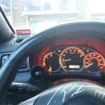
Premise: Use an Arduino, pressure sensor and other parts to create a customizable boost guage.
BOM | ||
$20 | Arduino Uno | |
$35 | Honeywell Pressure sensor | SSCDRRN030PDAA5 |
$0.75 | 7805 voltage regulator | |
$1 | Assorted resistors | |
$40.50 | Adafruit goodies | |
$6 | JST SM Plug + Receptacle Cable Set x4 | |
$13 | LCD display | |
$2.5 | Waterproof Polarized 4-Wire Cable Set | |
$10 | i2c / SPI character LCD backpack | |
$9 | Adafruit Perma-Proto Quarter-sized Breadboard PCB | |
$10 | misc wire | |
$5 | Tubing connector | |
Code |
Total: $112.50
Background information on the Arduino board: http://arduino.cc/en/Main/ArduinoBoardUno
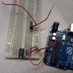
The Honeywell sensor I used has three leads - ground, positive data, and negative data (negative data just flips the voltage). Positive data goes to pin A0 on the Arduino. Recommend consulting the datasheet with your specific sensor - I used SSCDRRN030PDAA5, but significant construction benefits could be found using a sensor with a larger connector. I recommend staying with the SSC series - the NSC series, for example, is uncalibrated and outputs a raw signal, while the SSC series outputs e.g. 0-5 V. Slight changes to the math in the code might be necessary. FYI - The math in the code has been optimized by using integer math.
I used the Perma-Proto quarter-sized breadboard pcb to connect wires to the Honeywell sensor. I cut another one in half and used it for pin breakout on the Arduino board, as well as a place for the 7805 voltage regulator. The voltage regulator was used to drop the 12VDC commonly found in cars to 5VDC for the Arduino and Honeywell sensor. Since the voltage was now regulated, it was connected directly to the 5V pin of the Arduino board.
Theory and assembly of the i2c/SPI character LCD backpack and LCD screen can be found here: https://learn.adafruit.com/i2c-spi-lcd-backpack. The code I used was pretty much copy and pasted from there, using the same wire connections.
The i2c LCD backpack has been optimized by using the LiquidTWI library, shown here: http://www.youtube.com/watch?v=IpwqGJwn1FY (link to library is in video description)
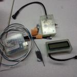
I used the JST SM plugs from Adafruit to connect the arduino and LCD screen circuits for ease of installation into the car. I used the Waterproof Polarized 4-Wire connector for the connection to the actual boost gauge circuit, since it was in the engine bay.
There is an option in the code for personal preference or debugging: on line 14, the code is:
boolean minmax = false; //flag for boost graph or max and min boost
The flag “false” can flipped to “true” to display the minimum (read: vacuum) and maximum boost levels since the gauge was last turned on.
I used an SLA to build the cases for everything - there is a box for the pressure sensor board, a box for the arduino, and a box for the display. The display box is a little small for my display, I had to widen it by about 1 mm all around. I also filled the pressure sensor board box with an electronics potting epoxy to protect the parts from any weather the car might see. STL part files here: https://www.dropbox.com/sh/ew7orezujg0shs8/AADgiSFyteHLHVaF0Uk0SBtVa
More ideas on the build: http://www.seatcupra.net/forums/showthread.php?t=348592


